The Basics of RFID Antennas
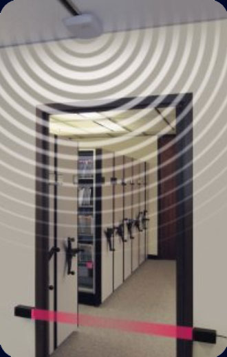
The RFID reader antenna transmits and receives waves that have both electrical and magnetic properties. These waves are called electromagnetic waves.
For a Project Manager it is important to understand RFID antennas and their place in the RFID ecosystem.
There are three basic types of RFID antennas:
- Linear or Dipole Polarization
- Monostatic Circular or Bistatic Circular
- Circular Polarization
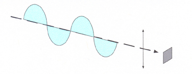
In the linear or dipole polarization antennas the electromagnetic wave propagates entirely in one plane – either vertical or horizontal –in the direction of the signal propagation. This is the antenna type to use if the tag orientation is known and fixed. The RFID antenna and RFID tag should be as closely matched as possible in polarization to get the longest and best read rates.
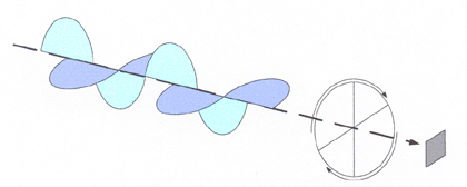
For circular polarization antennas the electromagnetic wave propagates in two planes creating a circular effect much like a corkscrew. This makes one complete revolution in a single wavelength timeframe. Since the circular RFID antenna continuously emits a wavelength, the rotational field will eventually cover any tag that is in its path. A circular antenna would be used when the tag orientation is not known. Circular polarization can be right or left handed hence you see the RHCP and LHCP options for the two types of complementary circular polarized antenna types.
The monostatic circular is the most common RFID antenna and uses a single common port to transmit and receive the radio signals. The bistatic circular type uses two RFID antennas in the same physical housing and uses one port to transmit and the other port to receive.
The monostatic RFID readers used with this type of antenna can be one, two, or four port readers. An alternate configuration can be a five port reader with a Listen-Before-Talk (LBT) port. On the monostatic readers the port transmits first and then receives signals on the same port.
The bistatic RFID readers usually have eight ports with four for transmitting and four for receiving. Each port is always active either transmitting or receiving the radio signals.
A reader is attached to its antenna with a coaxial cable. Depending on the quality and length of the cable a certain amount of power between the reader and the antenna is lost. This is called “line loss”. Higher quality (low noise) cable reduces the amount of line loss and allows for longer cable runs while providing maximum power to the antenna from the reader. The antenna usually provides gain to make up for what the line loss is between the reader and the cable.
The RFID antenna propagates the wave in both vertical and horizontal dimensions. The field coverage of the wave and also its signal strength is partially controlled by the number of degrees that the wave expands as it leaves the antenna. While the higher number of degrees means a bigger wave coverage pattern it also means lower strength of the signal.
Two important RFID antenna terms are azimuth (AZ) and elevation (EL).
AZ is the horizontal radiation plane of the antenna wave and is expressed in degrees to depict the amount of expansion horizontally from the centerline of the antenna at a maximum variation of 3 dB. This deviation of 3 dB is also known as “beamwidth”. An antenna will experience a 50% loss of signal strength when near or at the 3 dB Beamwidth angle.
EL is the vertical radiation plane of the antenna and also uses degrees to depict the amount of expansion vertically from centerline of the antenna at a maximum variation of 3 dB. Note the same signal strength information applies for the EL beamwidth as the AZ beamwidth.
Both Linear and circular antenna can have different AZ and EL degrees. This provides different read patterns depending on your requirements. The larger the number of degrees the wider the wave read zone and thus the lower the wave signal strength. The RFID antenna gain and the radiation plane width are mutually dependent and the larger the gain, the narrower the radiation plane. Where the AZ and EL are not identical in degrees the wider side controls the narrower plane.
For your next RFID project the selection of the proper antenna is one of the key activities in preparing for deploying your application.
For additional information on RFID antennas contact us at the Gateway RFID store.